Overview
The problem that governed my Capstone Project was the need to replace a failing hydraulic cylinder test bench. The goal of the project was to create a new test bench for our client so that they can test recently repaired and refurbished hydraulic cylinders, ensuring that the repairs made to the cylinders are effective and that the cylinders are safe to use again.
Objectives
The main objectives of the project were to develop a bench that was automated and just needed the operator to scan in the work order number and input their name, leaving the operation and data logging of the test in control of a PLC. A secondary objective of the project was to create a Python program that automatically generates a test report from the data logged by the HMI.
Outcomes
The outcome of the project is a new test bench that is being commissioned at our client's facility. The PLC and HMI were successfully programmed to control the electrical and hydraulic systems that control the flow of the hydraulic fluid while recording the data from multiple sensors, each with a unique purpose. This data can then be used by the Python program to create a test report for every cylinder tested using the bench.
My Contributions
I contributed to the project in multiple stages. The first stage involved designing the electrical circuits that control the hydraulic fluid in the bench, producing technical drawings, and a Bill of Materials (BOM) that were used to build and commission the bench. In the second stage of the project, I was in charge of developing the Python program that generates the test reports for each cylinder that was tested. I also aided in securing a 3D printed model for the presentations. Other minor contributions were that I aided my group members in creating reports and presentations, filling in the information relevant to my work on the project.
Process
The project progressed through multiple stages, with new challenges developing in each stage as we worked towards completing the final product. At the end of the project, our final design was handed over to our client before the end of March.
Stage 1: Initial Planning
At the beginning of the project, we met with our client to determine the specifications and requirements for the bench. This gave us a starting point for our research and development. Utilizing tools and information sources such as YouTube, various websites, professors, and the University's library, we developed an overview of what parts were required for both the electrical and mechanical portions of the project. This stage of the project took place throughout September.
Stage 2: Design and Development
The second stage of the project involved designing the electrical circuits that would control the hydraulic fluid in the bench. This involved researching and selecting the parts required to meet the bench's technical and functional requirements. After selecting the parts needed to realize the bench, I helped in creating technical drawings and a Bill of Materials (BOM) that were used to build and commission the bench. The mechanical portion of the project was also developed during this stage by other group members. This stage of the project was the most time consuming and took place from October to the middle of December, where we had a couple of meetings with our client to refine the scope of the project, ensuring that our designs were going to meet our client's needs. Unfortunately, due to a non-disclosure agreement with our client I am not sure what parts of the electrical design I can share on my portfolio website. If you would like to discuss the electrical design of the project please feel free to contact me and I would be happy to discuss.
Stage 3: Programming
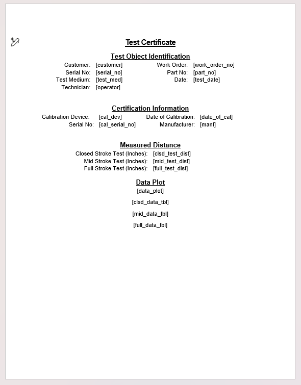
In the third stage of the project, I worked on developing a Python program to generate reports containing the data from each cylinder test. This stage of the project was the most challenging as it required studying Python and learning how to sort through the data produced by the PLC and HMI programming, shown in Figure 1. I had to work together with my group members to ensure that the PLC and HMI programming worked seamlessly together. We made several revisions to the output of the HMI programming, initially starting with the data being stored in 2 files, but by the end of the project, the HMI produces 4 data files. This led to multiple changes in the Python program to ensure that the data was being sorted out of the different files correctly. Allowing the Python program to generate the required graphs and tables for the test report. Figure 1 shows examples of the .txt files that are produced by the HMI, the data contained is arbitrary and does not represent any real test data. It is just an example of the format of the data files to demonstrate what the program is using to generate the test reports. Figure 2 shows an example of a Word document that serves as the template that the program fills to create each report, using keys.
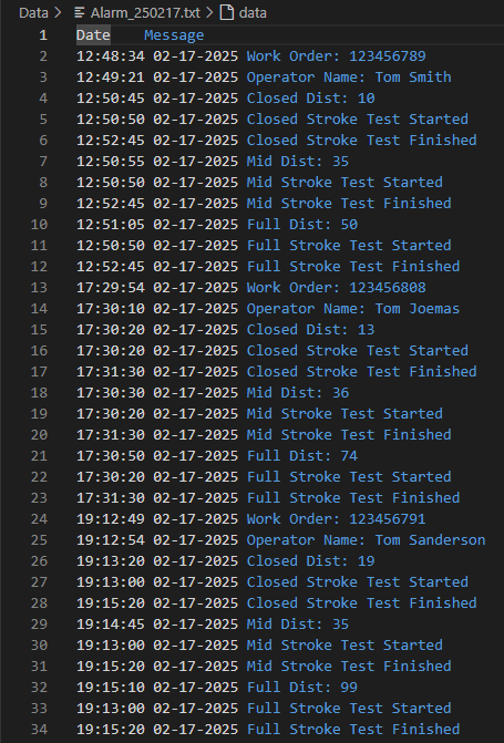
(a)
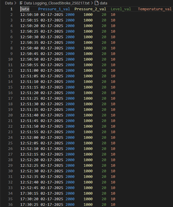
(b)